


Getting the right motor and battery
I realised early I'd paid almost twice the price for the motor and controller from a local reseller in relation to what I could have done through the official online retailer. Though I value the experience the reseller had with electric applications in marine environment and the helpful support they have offered, I have seen many "experts" charge handsomely for their expertise.
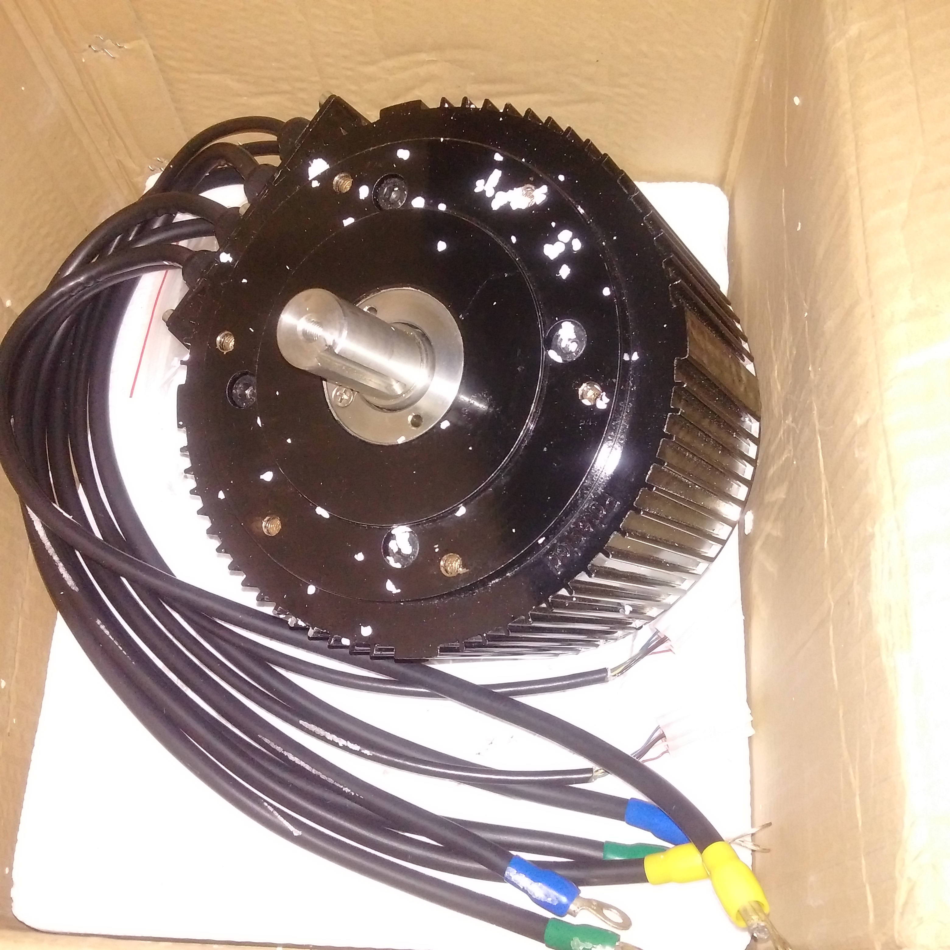
The motor and controller are from Golden Motors in China and consist of a brush less DC motor (BLDC), essentially an AC motor which is supplied with square pulsed AC in 3 phases, and a 500 A digital controller supplied by the batteries. Brushless motors offers greater reliability than brushed motors, this one also has a very high peak efficiency of 91%.
Installating the motor
To use the original combined throttle and gear lever I connected the old throttle cable to a "hall effect" throttle located in the motor compartment. To regenerate power I put the gear lever in reverse. The regenerative capability is very limited though.
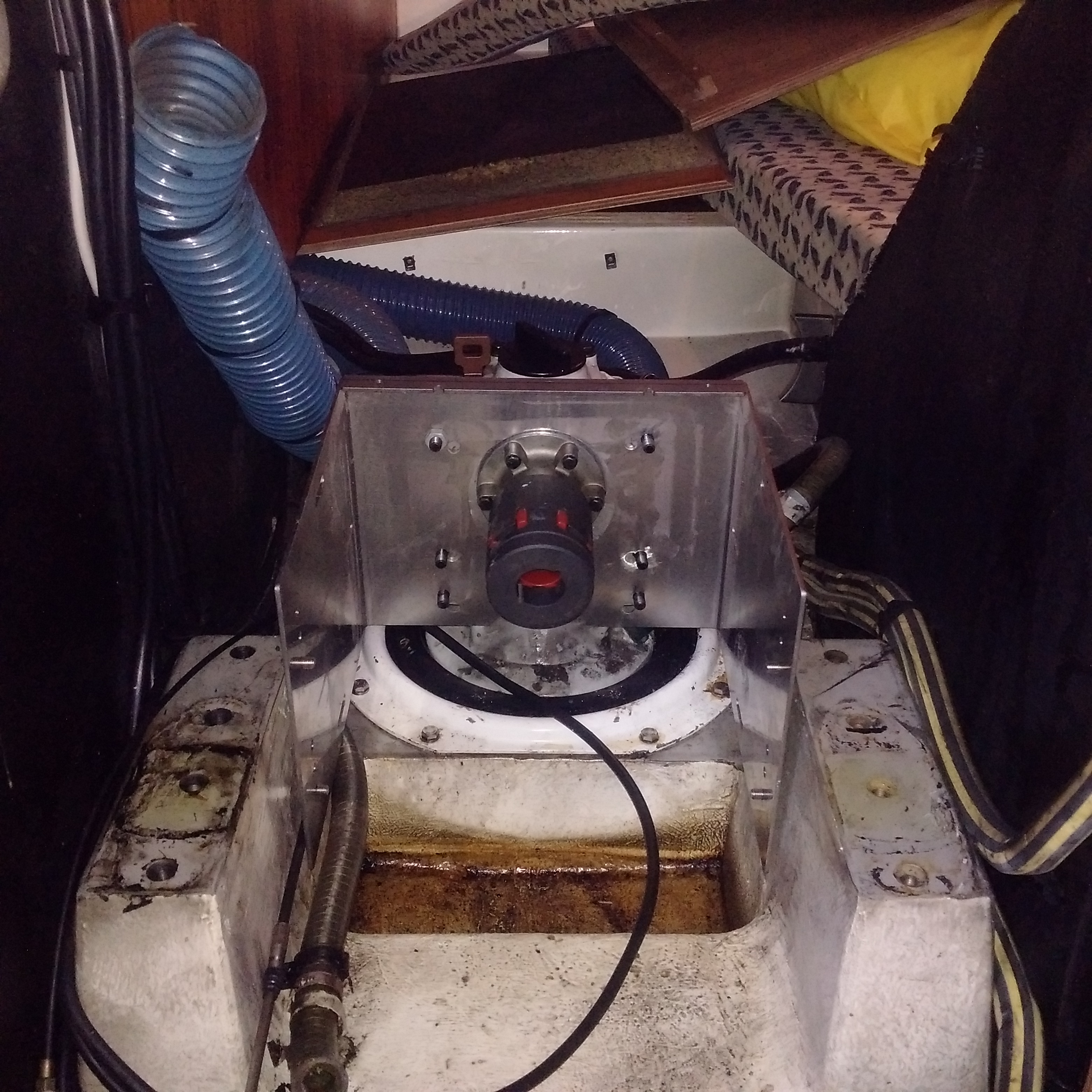
The motor is mounted onto a custom made stainless steel chassis bolted onto the old Volvo Penta 120S-E Sail drive and supported by the two old engine mount cushions. The drive and motor is connected with a two part splined adapter with a rubber bushing between them for vibration damping. This little piece has given me some grief as I failed to secure it from slipping fore and aft on the shafts. I also fitted a neopren seal between the motor and chassis for the dual purpose of taking up vibration and to prevent galvanic corrosion as the motor case is of aluminium.
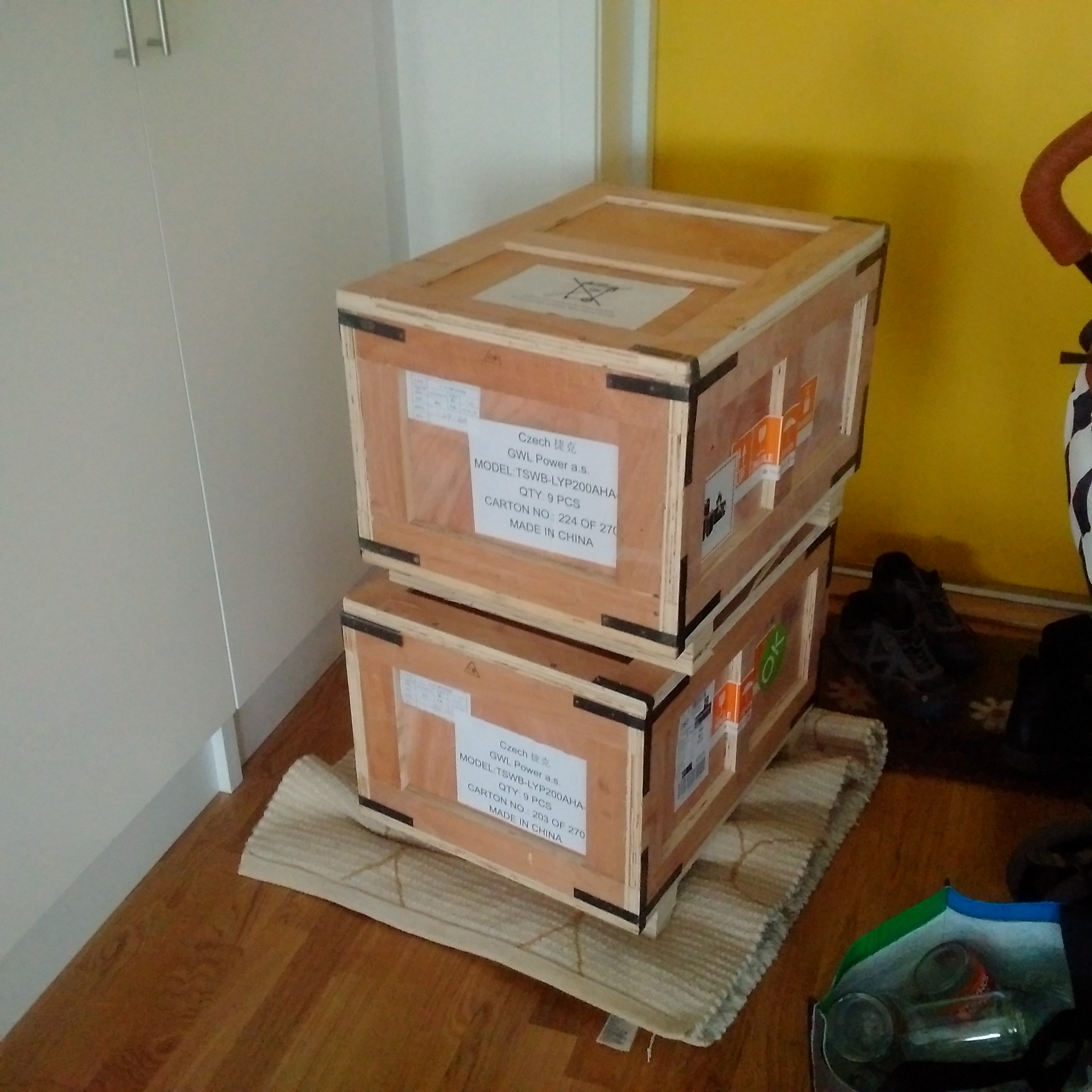
Finding space for the battery
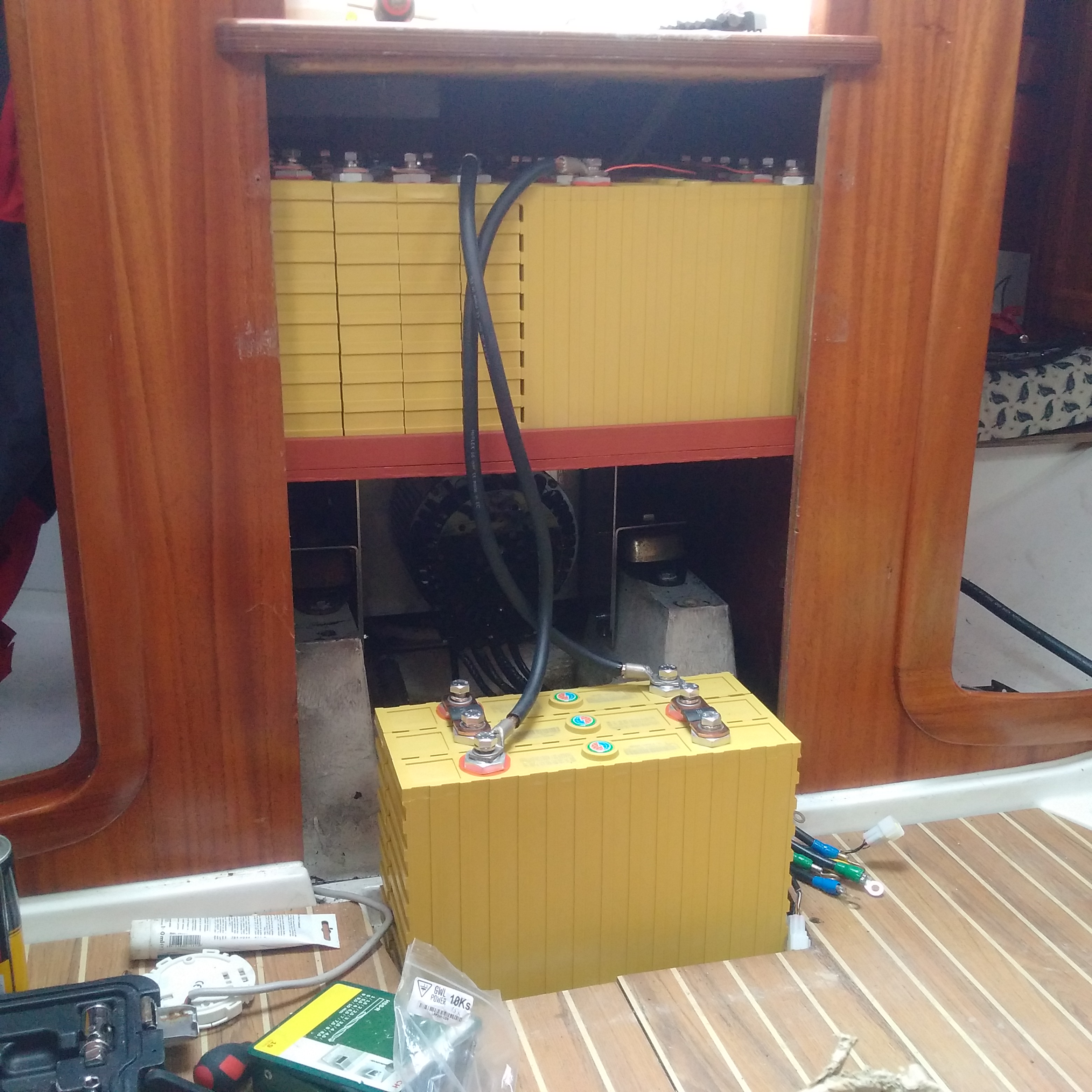
Careful consideration was given to the placement of the battery cells. Power loss in long cables, balance of the boat, easy access and fire fighting was the main concerns. I have seen professionally done conversion where the battery banks have been placed underneat the salong benches which misses all these criterias. Unable to find room around the motor I decided to place what I could on an aluminium plate above, leaving 3 cells in front of the motor where the old house battery was located.
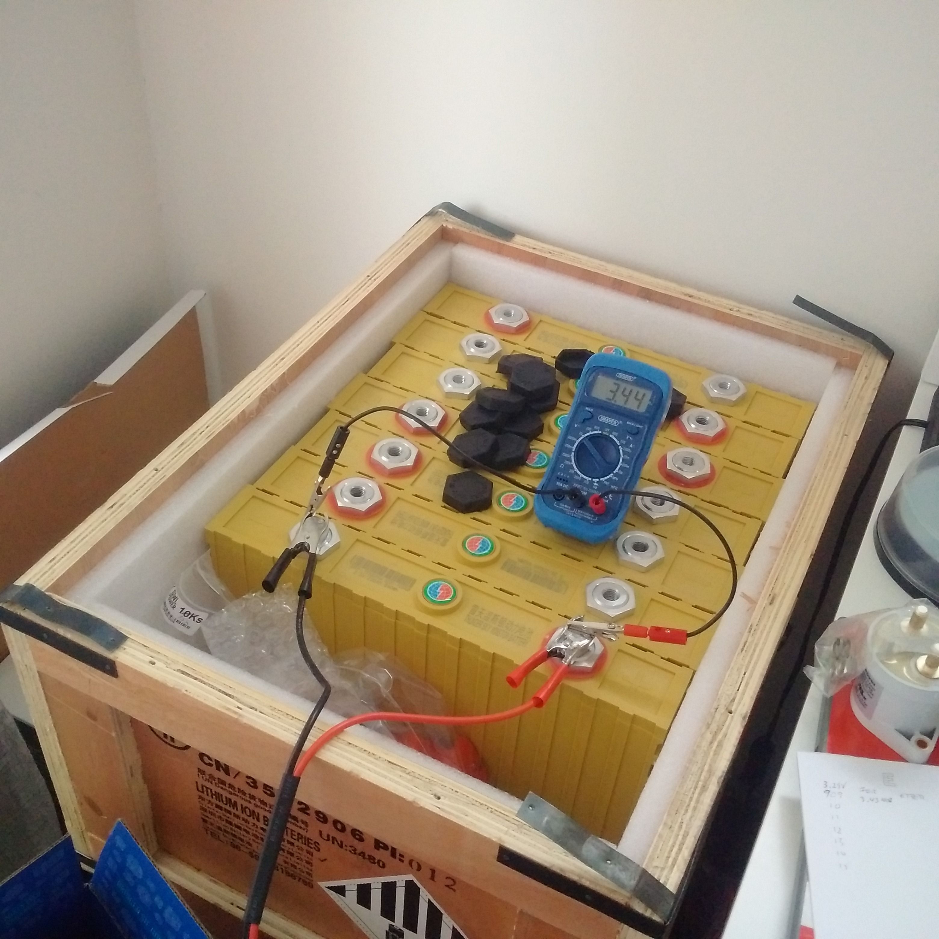
The battery bank is comprised of 16 Thundersky Winston LiFePo4 cells which are tested to withstand in excess of 7000 cycles at 80% DOD and 8000 cycles at 70% DOD.
Evaluation
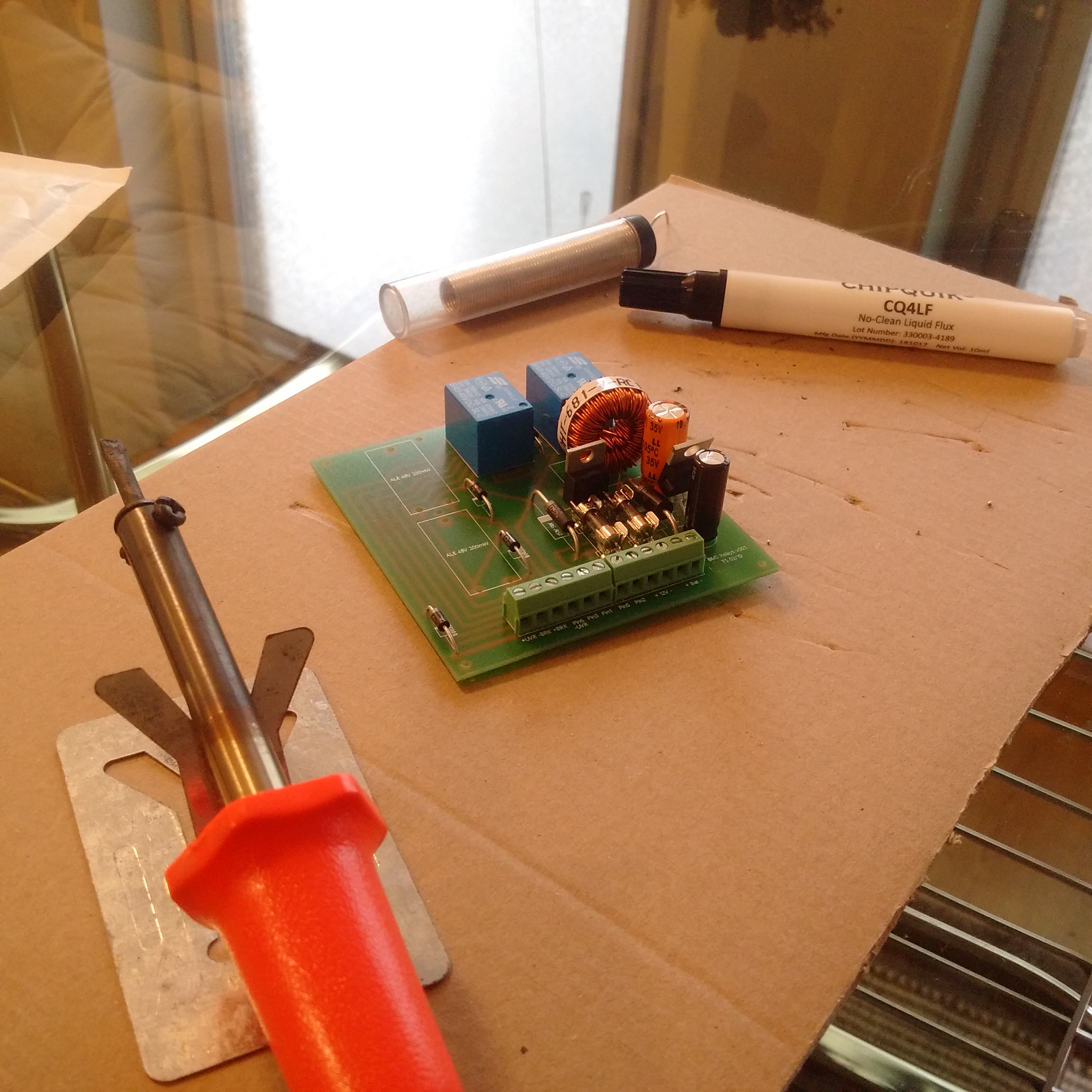
The overheat protection in the motor, in the motor controller as well as 3 sensors on the cells connected to the BMS will give early warnings of an overheat condition. And the benefits of this battery location is that it enables utilisation of the original squirt hole for the fire extinguisher in the companionway steps for the entire system, as well as leave the centre of gravity if not better at least very near the same location as before the conversion. more...
Before
- 112kg - Diesel Engine
- 50kg - Led Acid Batteries
- 80kg - 90l diesel tank
- 40kg - Accessories
- 282kg - Sum
After
- 117kg - LiFePo4 cells
- 17kg - Electric motor
- 12kg - Chassis
- 2,5kg - Motor controller
- 10kg - Accessories
- 158,5kg - Sum